Hello, I’m Tommy and I spent one week here at Embecosm for my work experience, where I learnt a lot and completed many projects with the immense amount of material I had available to me. I worked along with Peter and Daniel, who were both doing their work experience here as well.
The Blink Circuit
I came here with only the bare Arduino basics, even though I have one myself. So we all completed a simple project which would give us a start in how to wire up an Arduino and do some basic programming — the LED blink.
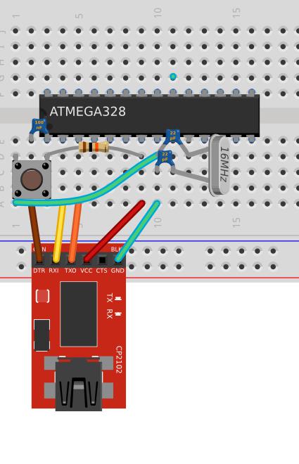
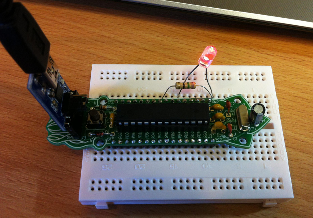
This was made using a “Shrimp” circuit, as shown below.
After building this all that needed to be added was a resistor and a LED to create the blink circuit.
Once programmed I managed to make the LED blink, which was quite rewarding.
The Sensor Car
After completing the blink circuit we moved onto something more complicated: building an Arduino sensor controlled car.
We were given the Sunfounder sensor kit, which could be used on the car with sensors such as tilt, and heat, and infrared transmitters and receivers and so on. However, the first task was to build the car and make sure it could work. We had a base to use of an old RC car with four wheels, two with a motor for the forwards and backwards, and two wheels which had a motor which would make them turn. However, none of this was wired up.
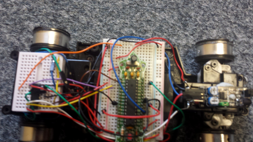
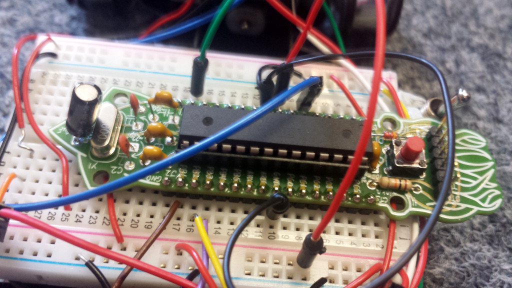
First we added a breadboard to the car and wired up a Shrimp circuit. Then added another breadboard to the back of the car, which is where the H bridge was located. This would connect up all of the motors and give them power. This did not work at first as there was too much electrical noise, but there was an easy way to fix by modifying the shrimp into a “Protected Shrimp”. This added more capacitors and another resistor to the Shrimp design to remove some of the electrical noise. After which we programmed the car to go forwards for a few seconds, and then backwards for a few seconds.
Next came the steering, which was done by connecting the steering motor with the H bridge. By programming the car to turn left and right every few seconds, the steering worked.
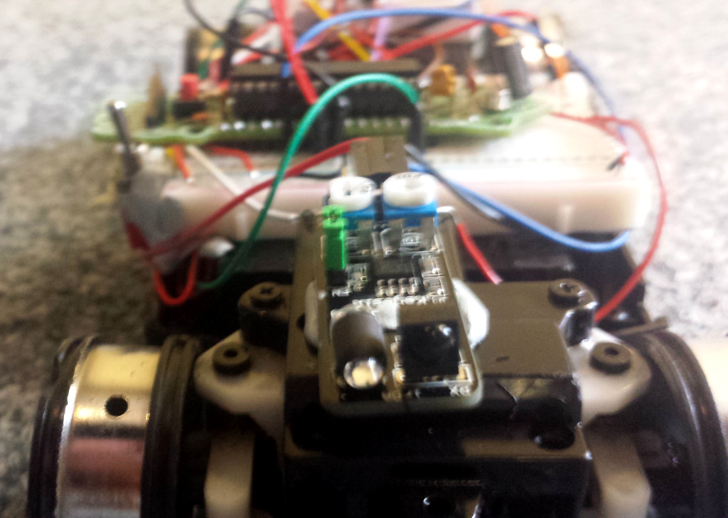
Now came adding the sensor. The sensor we chose to use was the Obstacle Avoidance Sensor. This would send out a signal if something was in front of it. It did this by sending out infrared light and if there was an object within about 10cm in front of it, the infrared light was reflected off the object and sent back to the infrared receiver and sent out a signal. We programmed this so that when the signal was sent it would make the car reverse and turn away from where it was facing, so that it would then try a different direction. We programmed the car to only go forward if there was no signal from the sensor, so that it would go straight until it came close to something.
Now the sensor car was fully functional, however, there were a few problems with the car which needed to be fixed.
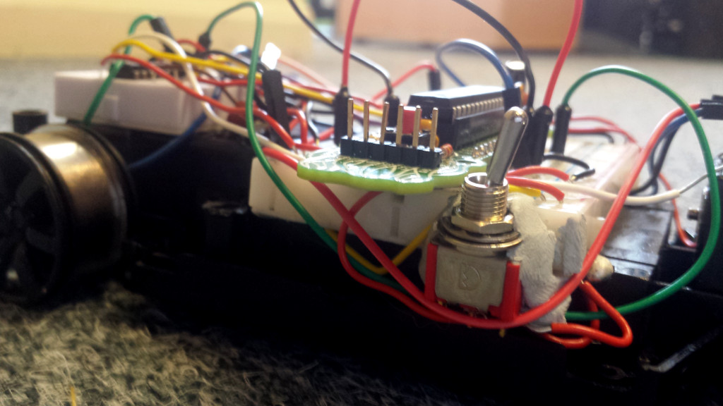
The first one was that if you wanted to turn the car on or off, you would have to plug in or take out a cable, as the power came straight from the battery pack. So I found a switch and wired this up to the power cable and into the breadboard. This meant all that was needed to turn the car on or off was to flick the switch on the side.
Another problem that needed to be fixed was that all the wiring was done with the same length male-to-male wires, and so there were wires everywhere and it was a big mess. So I replaced all the wires with perfectly cut wires so that they were not going everywhere.
Unfortunately the battery life is very short, so the batteries need to be replaced quite often. However, the car works very well.
Here is the car finished, with the obstacle avoidance sensor or the front.
We also attached a Cuttlefish circuit board to the car, as it is a tidier, soldered version of all the Protected Shrimp circuit.
Soldering the Cuttlefish
We all next learnt how to solder a circuit board and soldered our own Cuttlefish. This involved adding the smallest components to the circuit board first, and then going up in size until adding the 28 pin socket for the ATMEGA328 chip. The components I soldered included:
- An electrolytic capacitor
- 16MHz crystal
- Two 22pf capacitors
- Four 100nf capacitors
- A Tactile Switch
- A diode
- 10 kilo ohm resistor
- Two strips of 16 pin header
- A strip of 6 pin header
- A 28 pin socket and the ATMEGA328 chip
Once I had finished soldering the Cuttlefish, I wired it up on a breadboard with the blink circuit, to test if I had built and soldered the Cuttlefish correctly. It did not work at first, but I soon found out that I was missing a component and after soldering the last capacitor in the blink circuit worked.
IRC Bot
For our next project looked at what sensors could be used around the office and connected to the IRC bot, which would tell what the sensors are reading by typing a command. An IRC (Internet Relay Chat) bot is essentially an IRC client which has set functions or commands which it responds to when a user types the command in the chat. For example, you could tell when the kettle was boiled with a humidity sensor or a heat sensor, so when the temperature drops the IRC bot says “the kettle has boiled”.
We decided to create a command for the IRC bot in the office as it was an easy way to get to understand some of the programming behind it. The command was called “sp00ky” and would tell you how many ghosts were in the room. This is how it worked:
- The user would type “sp00ky” in IRC.
- The bot would pick a random number between 1 and 4.
- Using whatever number it picked, it would then select that many names out of a large list. For example, if it came up with the random number 3, then it would choose 3 names out of the list.
- It would then say in the IRC, for example, “Ghosts currently in room: The ghost of JFK, the ghost of Guy Fawkes, The Woman In Black”
This was just a simple command to get to know how the IRC bot works and to get some basic knowledge in programming it.
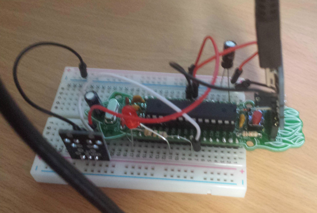
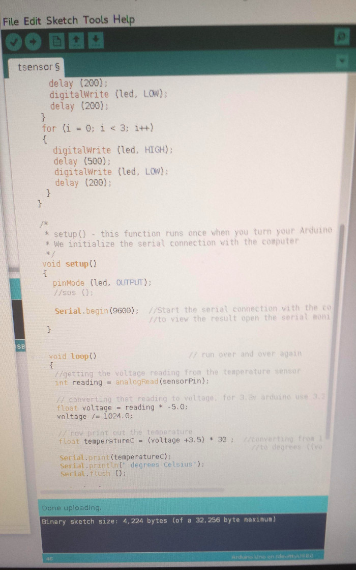
We then went on to trying to link one of the sensors with the IRC Bot. The one which came straight to us as the best choice of sensor was the heat sensor. The idea was to link the heat sensor with the IRC bot so that when a command was typed, it would give the temperature in the room.
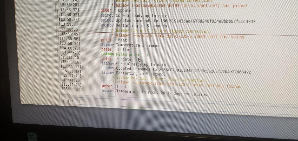
The command was !heat, and it displayed the temperature in the room. There were a lot of problems when making this as by default, Arduino resets when serial options are used.
Here is some of the code used for programming the Arduino temperature sensor.
Summary
Over the period of a week I learnt so much, from doing some basic Arduino programming, to creating a car that drives by itself and with sensor control, and using a Cuttlefish circuit board to attach a sensor to an IRC bot. All in just one week.
This has given me a good understanding of basic electronics and building circuits, and basic software engineering and programming. This experience will help me very much in the future, as it has confirmed that I want to continue doing computer science in education and then my career. It has also encouraged me to do projects like these and hopefully more complicated projects at home.
Everyone I worked with helped me if I got stuck or confused and really helped me understand everything I did over the week. Peter and Daniel were very good guys to work with, as we managed to complete all those projects as an effective team. Both of them came here probably knowing more than I did, but after this week, I feel we are all at the same level.
I’m certain that I would love to come back here sometime in the future. It was really an amazing experience, I have learnt an extraordinary amount and done many exciting projects with great people. It was a great week and I wish I could have done more.

